How to Implement a Kalman Filter for MPU6050 Calibration on STM32F4 Quadcopter
Why Your Quadcopter Needs a Kalman Filter for the MPU6050
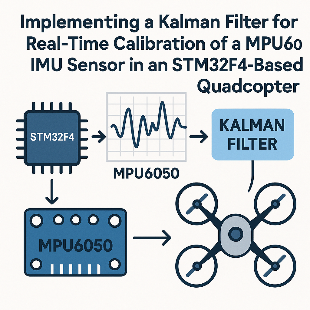
Raw MPU6050 readings are noisy. The gyroscope drifts over time, and the accelerometer is jittery and sensitive to vibration, which quadcopters produce in abundance. Neither source alone gives you a reliable angle estimate. A Kalman filter fuses both: it trusts the gyroscope for short-term angular changes and uses the accelerometer to correct long-term drift. The result is a smooth, accurate orientation estimate that your flight controller can actually use.
This walkthrough covers a simplified 1D Kalman filter for a single axis (pitch or roll). It's the right starting point. Once you understand the math on one axis, extending to a full 2D or 3D filter is mostly bookkeeping.
Prerequisites
- Solid C programming skills and comfort with embedded development
- Experience with STM32CubeIDE v1.16+ and the STM32 HAL
- Basic understanding of what a Kalman filter does (predict-update cycle)
- An STM32F4 board and an MPU6050 breakout
Parts/Tools
- STM32F4 development board (Nucleo-F411RE, STM32F4 Discovery, or similar)
- MPU6050 IMU breakout board (GY-521 is the most common)
- STM32CubeIDE v1.16+
- Jumper wires and breadboard
Steps
- Wire the MPU6050 to Your STM32F4
Standard I2C hookup. The MPU6050 runs on 3.3V, which matches the STM32F4 directly:
STM32F4 Pin    MPU6050 Pin
-----------    -----------
PB7 (SDA)      SDA
PB6 (SCL)      SCL
3.3V           VCC
GND            GND
The GY-521 board has built-in pull-ups on SDA and SCL. If you're using a different breakout, add 4.7k pull-ups to 3.3V on both lines. Without proper pull-ups, I2C is unreliable and you'll waste hours thinking your code is broken.
The MPU6050's default I2C address is 0x68 (AD0 pulled low). If AD0 is high, it's 0x69.
- Set Up the STM32CubeIDE Project
Create a new project for your F4 chip. In the .ioc configurator:
- Enable I2C1 (or whichever I2C peripheral matches your pin choice).
- Set the I2C speed to 400 kHz (Fast Mode). The MPU6050 supports it, and you want the fastest reads possible for a flight controller.
- Set up a timer or use
HAL_GetTick()for timestamping. The Kalman filter needs to know the time delta between updates.
Generate the code and make sure it compiles clean before adding sensor code.
- Read Raw Sensor Data from the MPU6050
First, wake up the MPU6050. It starts in sleep mode by default:
void MPU6050_Init(void) {
    uint8_t data = 0x00;
    HAL_I2C_Mem_Write(&hi2c1, MPU6050_ADDR << 1, 0x6B, 1, &data, 1, 100);

    // Set gyro range to +/-250 deg/s for best sensitivity
    data = 0x00;
    HAL_I2C_Mem_Write(&hi2c1, MPU6050_ADDR << 1, 0x1B, 1, &data, 1, 100);

    // Set accel range to +/-2g
    data = 0x00;
    HAL_I2C_Mem_Write(&hi2c1, MPU6050_ADDR << 1, 0x1C, 1, &data, 1, 100);
}
Then read all 14 bytes of sensor data in one burst. This grabs accel X/Y/Z, temperature, and gyro X/Y/Z:
void MPU6050_Read_Data(int16_t *ax, int16_t *ay, int16_t *az,
                       int16_t *gx, int16_t *gy, int16_t *gz) {
    uint8_t data[14];
    HAL_I2C_Mem_Read(&hi2c1, MPU6050_ADDR << 1, 0x3B, 1, data, 14, 100);
    *ax = (data[0] << 8) | data[1];
    *ay = (data[2] << 8) | data[3];
    *az = (data[4] << 8) | data[5];
    // data[6..7] is temperature, skip it
    *gx = (data[8] << 8) | data[9];
    *gy = (data[10] << 8) | data[11];
    *gz = (data[12] << 8) | data[13];
}
Watch out: the raw values need scaling. At +/-250 deg/s, divide gyro values by 131.0 to get degrees per second. At +/-2g, divide accel values by 16384.0 to get g-force.
- Implement the Kalman Filter
Here's a clean, minimal Kalman filter struct and the two key functions. This is a 1D filter for a single angle (pitch or roll):
typedef struct {
    float q_angle;   // Process noise for the angle
    float q_bias;    // Process noise for the gyro bias
    float r_measure; // Measurement noise (accelerometer)
    float angle;     // Current angle estimate
    float bias;      // Current gyro bias estimate
    float P[2][2];   // Error covariance matrix
} KalmanFilter;
void Kalman_Init(KalmanFilter *kf) { kf->q_angle = 0.001f; kf->q_bias = 0.003f; kf->r_measure = 0.03f; kf->angle = 0.0f; kf->bias = 0.0f; kf->P[0][0] = 0.0f; kf->P[0][1] = 0.0f; kf->P[1][0] = 0.0f; kf->P[1][1] = 0.0f; }The update function takes a gyro rate (in deg/s) and an accelerometer-derived angle (in degrees), plus the time step:
float Kalman_Update(KalmanFilter *kf, float newAngle, float newRate, float dt) {
    // --- Predict ---
    kf->angle += dt * (newRate - kf->bias);

    kf->P[0][0] += dt * (dt * kf->P[1][1] - kf->P[0][1] - kf->P[1][0] + kf->q_angle);
    kf->P[0][1] -= dt * kf->P[1][1];
    kf->P[1][0] -= dt * kf->P[1][1];
    kf->P[1][1] += kf->q_bias * dt;

    // --- Update ---
    float S = kf->P[0][0] + kf->r_measure;
    float K[2];
    K[0] = kf->P[0][0] / S;
    K[1] = kf->P[1][0] / S;

    float y = newAngle - kf->angle;
    kf->angle += K[0] * y;
    kf->bias += K[1] * y;

    float P00_temp = kf->P[0][0];
    float P01_temp = kf->P[0][1];
    kf->P[0][0] -= K[0] * P00_temp;
    kf->P[0][1] -= K[0] * P01_temp;
    kf->P[1][0] -= K[1] * P00_temp;
    kf->P[1][1] -= K[1] * P01_temp;

    return kf->angle;
}
This version tracks gyro bias, which is the real advantage over a simple complementary filter. The bias estimate adapts as the gyroscope drifts, keeping your angle accurate over long periods.
- Put It All Together and Test
In your main loop, read the sensor, compute the accelerometer angle, and feed both into the Kalman filter:
KalmanFilter kfPitch;
Kalman_Init(&kfPitch);

uint32_t prevTick = HAL_GetTick();

while (1) {
    int16_t ax, ay, az, gx, gy, gz;
    MPU6050_Read_Data(&ax, &ay, &az, &gx, &gy, &gz);

    // Accelerometer-based pitch angle
    float accelPitch = atan2f((float)ay, (float)az) * 180.0f / M_PI;

    // Gyro rate in deg/s (at +/-250 range)
    float gyroRateX = (float)gx / 131.0f;

    uint32_t now = HAL_GetTick();
    float dt = (now - prevTick) / 1000.0f;
    prevTick = now;

    float pitch = Kalman_Update(&kfPitch, accelPitch, gyroRateX, dt);

    // Use 'pitch' for your flight controller
}
For initial testing, skip the quadcopter. Hold the sensor board in your hand, tilt it slowly, and print the filtered angle over UART. Compare it to the raw accelerometer angle. You should see the Kalman output is much smoother and doesn't freak out when you shake the board (simulating motor vibration).
Tuning tip: if the filter responds too slowly, decrease
r_measure. If it's too jittery, increase it. Theq_angleandq_biasvalues rarely need much adjustment from the defaults above, but every sensor and mounting setup is a little different.
Troubleshooting
- No response from MPU6050 over I2C
- Verify the I2C address. Try both 0x68 and 0x69. Use an I2C scanner sketch to confirm the device is present on the bus.
- Check pull-up resistors and wiring. SDA and SCL need pull-ups, and the connections must be solid. Loose breadboard jumpers cause intermittent failures.
- Make sure you're left-shifting the address by 1 in HAL calls (
MPU6050_ADDR << 1). The HAL expects the 8-bit address format.
- Angle readings drift or oscillate
- Tune the noise parameters. Start with the defaults above, then adjust
r_measurefirst. A value that's too low trusts the noisy accelerometer too much; too high and the filter ignores accelerometer corrections, letting gyro drift accumulate. - Make sure your
dtcalculation is correct. If the time step is wrong, the gyro integration will be off and the filter can't compensate. - Calibrate gyro offsets at startup: take 1000 readings while the sensor is stationary and subtract the average from subsequent readings.
- Tune the noise parameters. Start with the defaults above, then adjust
Where to Go From Here
This 1D Kalman filter handles pitch (or roll) on a single axis. For a real quadcopter, you'll want one filter per axis, or step up to a full complementary filter or an extended Kalman filter (EKF) that handles all three axes simultaneously. The MPU6050 also has an onboard Digital Motion Processor (DMP) that does sensor fusion in hardware, but I find implementing it yourself gives you much more control over tuning and behavior. Either way, the concepts here are the foundation for any IMU-based attitude estimation.