The infamous “blinky” program is one that has stood the test of time, and is meant to validate hardware, software, and serve as a basis for all future development. Almost all embedded developers have started with this simple blink program, which aims to make an LED light up using hardware. This project serves as a start to your embedded journey.
Get Started:
Looking to get started with embedded systems? We recommend some of the essential tools and boards that every engineer and hobbyist should have on their bench.
Arduino Uno – https://amzn.to/3JkjAXi
Must have Elegoo Starter Kit – https://amzn.to/3JmaKbf
The Elegoo Uno works exactly like the Arduino Uno, same framework and everything! Only, it is cheaper.
Another Option – https://amzn.to/45jl6Bq
1. Overview & Goals
This project demonstrates how to control an LED with an Arduino Uno using a simple digital output.
You’ll learn:
- How to connect an LED safely to an Arduino GPIO pin.
- How to write and upload Arduino code to blink an LED.
- The basic principles of current limiting and digital I/O.
This is the foundation for all more advanced Arduino-based control projects.
2. System Architecture
Block Diagram:
[PC + Arduino IDE] –> USB Serial –> [Arduino Uno] –> GPIO Pin –> [LED + Resistor] –> GND
- Arduino Uno acts as the microcontroller.
- GPIO pin outputs HIGH (5 V) or LOW (0 V) to control LED.
- Resistor limits current to safe levels.
- USB provides programming interface and power.
3. Bill of Materials (BOM)
| Item | Qty | Part Number / Spec | Vendor Example Link |
| Arduino Uno R3 | 1 | ATmega328P-based | Arduino Store |
| LED (5 mm, red) | 1 | Vf ~ 2 V, If ~ 20 mA | Adafruit |
| Resistor | 1 | 220 Ω ±5%, ¼ W | Digi-Key |
| Breadboard | 1 | Standard 400 tie-points | Amazon / Adafruit |
| Jumper Wires (Male–Male) | 3 | 20–22 AWG | Amazon / Adafruit |
| USB Cable | 1 | USB Type-B | Included with Arduino |
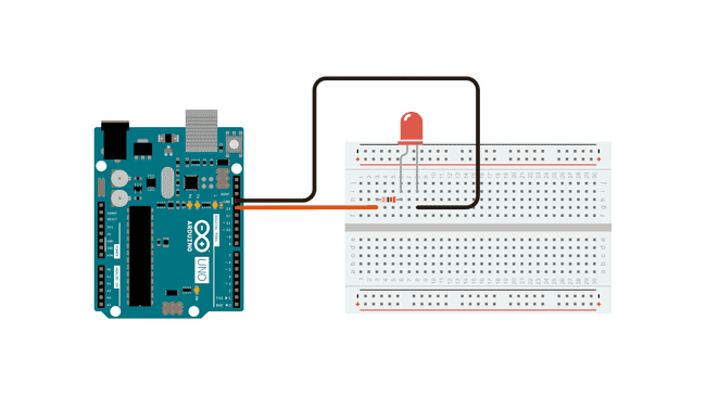
4. Hardware Setup
Electrical Schematic:
+5V (Arduino GPIO pin 13)
│
│
[220Ω]
│
[ LED ]
│
GND
Pin Mapping Table:
| Arduino Pin | Connection | Notes |
| D13 | Resistor → LED Anode (+) | Built-in LED also connected here |
| GND | LED Cathode (–) | Common ground |
Wiring Steps:
- Place the LED on the breadboard. Identify the anode (long lead, +) and cathode (short lead, –).
- Connect the anode to one end of the 220 Ω resistor.
- Connect the other end of the resistor to digital pin 13 on the Arduino.
- Connect the LED cathode to Arduino GND.
5. Firmware / Software Bring-Up
5.1 Install Arduino IDE
- Download from https://www.arduino.cc/en/software
- Install drivers if prompted.
5.2 Write the Program
Complete Arduino Code:
// Arduino LED Blink Example

// Blinks LED on pin 13 at 1 Hz

#define LED_PIN 13  // GPIO pin connected to LED

void setup() {

  pinMode(LED_PIN, OUTPUT); // Set pin as output

}

void loop() {

  digitalWrite(LED_PIN, HIGH); // Turn LED on

  delay(500);                  // Wait 500 ms

  digitalWrite(LED_PIN, LOW);  // Turn LED off

  delay(500);                  // Wait 500 ms

}
5.3 Upload to Arduino
- Connect Arduino via USB.
- In Arduino IDE:
- Select Tools → Board → Arduino Uno.
- Select Tools → Port for your device.
- Select Tools → Board → Arduino Uno.
- Click Upload (right arrow icon).
6. Integration Process
- With the wiring done and code uploaded, the Arduino will power the LED directly from GPIO pin 13.
- The LED will blink on and off every 0.5 seconds.
Troubleshooting:
- LED not lighting: Check polarity of LED and resistor connections.
- LED very dim: Verify resistor value is not too high (use 220 Ω).
- Compile errors: Ensure correct board is selected in Arduino IDE.
7. End-to-End Testing
- Expected behavior: LED turns on for 0.5 seconds, off for 0.5 seconds, repeatedly.
- Use the built-in LED on pin 13 as a secondary check—if it blinks, the code works even if your external LED wiring is wrong.
8. Performance & Reliability Notes
- Pin 13 has a built-in LED and resistor, but still use an external resistor for your added LED to avoid overcurrent.
- Do not draw more than 40 mA from a single GPIO pin—standard LED with 220 Ω is safe (~14 mA).
9. Next Steps & Extensions
- Control multiple LEDs by assigning different pins.
- Use analogWrite() for brightness control (PWM).
- Trigger LED using a button press.
- Replace LED with a relay or transistor to control larger loads.