12 Proven Steps to Master baremetal programming on STM32 and how to understand what you are doing (Ultimate Guide)
How to start baremetal programming on STM32 and how to understand what you are doing—this no‑nonsense guide walks you through toolchains, registers, clock setup, interrupts, debugging, and best practices so you can ship reliable firmware with confidence.
Getting the Correct Hardware
Choosing the correct hardware is essential to a smooth learning process. I really recommend getting the STM32F401RE because of its cheapness, reliability, and small physical footprint. I have used this board countless times and I find it has very straightforward capabilities; it can serve as a starter discovery board as well as in industry. STM32s are widely used in industry as the staple Microcontroller.
Required Hardware for this Tutorial:
– STM32F401RE – https://amzn.to/4fDfLZ2
– USB Mini-b cable – https://amzn.to/4mNIAEr
Understanding Bare‑Metal on STM32: What It Really Means
When people say “bare‑metal,” they mean writing firmware that talks straight to the microcontroller’s registers—no operating system and, if you choose, no vendor drivers. In short, you’re in charge of startup code, clocking, memory layout, and peripheral configuration. That’s exactly why How to start baremetal programming on STM32 and how to understand what you are doing matters: you see what the silicon is doing and why.
Why this approach is powerful
- You learn the memory map, the reset flow, and how interrupts really fire.
- You don’t get surprised by hidden defaults in big libraries.
- You ship smaller, faster binaries—important for tight flash/RAM budgets.
And where higher layers still help
Bare‑metal doesn’t mean “never use helper code.” STM32’s LL (Low‑Layer) headers mirror registers closely and save typing. Even HAL can be fine once you understand the hardware underneath. The point is choice—and clarity.
Documents That Matter: Datasheet vs. Reference Manual vs. Programming Manual
To truly understand the chip, you must know which PDF answers which question.
- Datasheet: package, electricals, pinouts, memory sizes.
- Reference Manual (RM): peripherals in detail—GPIO, RCC, timers, DMA, SPI, I²C, USART, ADC, etc.
- (ARM) Programming Manual / Architecture Manual: Cortex‑M core specifics—NVIC, SysTick, exceptions, privilege, barriers, bit‑banding.
Pro tip: keep PDFs open side by side. When you touch a register, check the RM’s description and reset values. Keep the errata handy—saves hours.
- ST official docs portal: https://www.st.com (search your exact part, e.g., STM32F401RE).
- ARM Architecture docs: https://developer.arm.com/documentation/
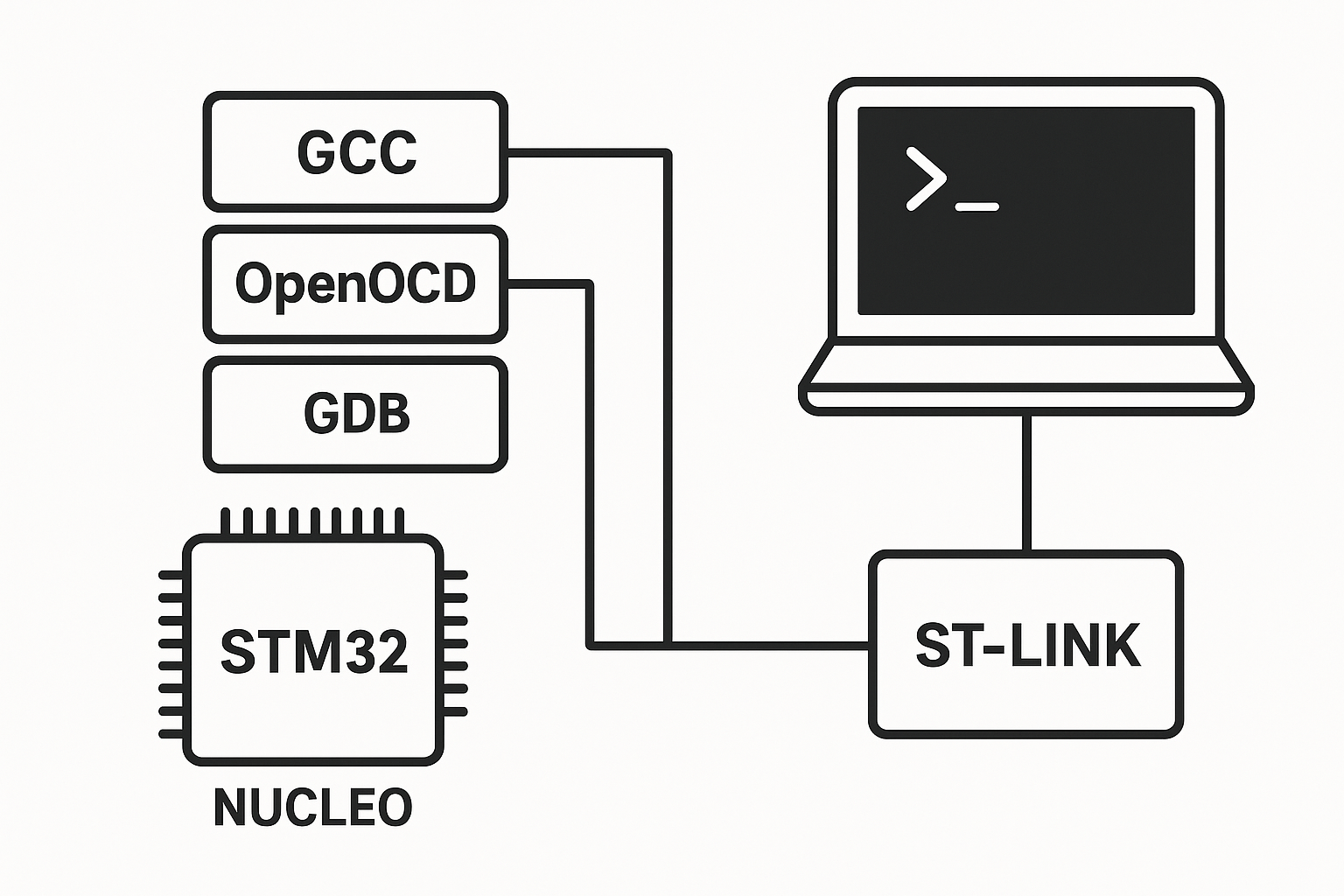
Setting Up Your Toolchain (GCC, CMake/Make, OpenOCD/ST‑Link, GDB)
You don’t need much to start:
- Compiler:
arm-none-eabi-gcc - Debugger/programmer: ST‑Link + OpenOCD (or ST’s own tools)
- Build system:
makeor CMake - Editor/IDE: anything comfortable (VS Code, CLion, STM32CubeIDE)
Minimal project structure
/project
  /src
    main.c
    startup_stm32.s
  /ld
    stm32f4_flash.ld
  Makefile
  openocd.cfg
Keep it small first. Add complexity only when you need it.
Moving away from STM32CubeIDE and the STMCubeMx Framework can be frightening at first; however, in industry, you will commonly be faced with huge codebases based on baremetal frameworks. These frameworks will have little to no documentation and can have a very steep learning curve; following this tutorial and learning the core concepts will be extremely helpful in industry.
How to start baremetal programming on STM32 and how to understand what you are doing — quick overview
- Pick a concrete board (e.g., Nucleo‑64 with an STM32F401RE).
- Gather PDFs: datasheet, RM, PM/ARM manual, errata.
- Install GCC, OpenOCD, and GDB.
- Create a startup file with a vector table and
Reset_Handler. - Write a linker script for FLASH/RAM and sections (
.isr_vector,.text,.data,.bss). - Blink an LED by setting GPIO registers—prove your toolchain and map are right.
- Add a debugger session: set breakpoints, inspect memory, watch registers.
- Learn SysTick and NVIC using the manuals, not guesswork.
- Log via SWO/ITM or UART to see real‑time values.
- Scale to timers/DMA only after the basics feel boring.
Building From Zero: Startup Code, Reset Handler, and Vector Table
Bare‑metal starts before main(). On reset, the CPU fetches the initial stack pointer and the address of Reset_Handler from the vector table at the start of FLASH.
Vector table & startup (simplified ARM assembly)
/* startup_stm32.s */
    .syntax unified
    .thumb

    .section .isr_vector, "a", %progbits
    .type   g_pfnVectors, %object
g_pfnVectors:
    .word   _estack                 /* Initial MSP value (from linker) */
    .word   Reset_Handler           /* Reset */
    .word   NMI_Handler
    .word   HardFault_Handler
    /* ... other core/system/peripheral vectors ... */

    .text
    .thumb_func
Reset_Handler:
    /* Copy .data from FLASH to RAM, zero .bss (done in C if you prefer) */
    bl SystemInit                   /* clocks, FPU, etc. (optional for now) */
    bl main
1:  b 1b                            /* if main returns, loop forever */

NMI_Handler:      b .
HardFault_Handler:b .
Linker script essentials (stm32f4_flash.ld, excerpt)
/* Memory layout: adjust for your part */
MEMORY
{
  FLASH (rx) : ORIGIN = 0x08000000, LENGTH = 512K
  RAM   (rwx): ORIGIN = 0x20000000, LENGTH = 96K
}

_estack = ORIGIN(RAM) + LENGTH(RAM); /* initial MSP */

SECTIONS
{
  .isr_vector : {
    KEEP(*(.isr_vector))
  } > FLASH

  .text : {
    *(.text*) *(.rodata*)
  } > FLASH

  .data : AT (ADDR(.text) + SIZEOF(.text)) {
    _sdata = .; *(.data*) _edata = .;
  } > RAM
  _sidata = LOADADDR(.data);

  .bss (NOLOAD) : {
    _sbss = .; *(.bss*) *(COMMON) _ebss = .;
  } > RAM
}
This layout ensures the CPU starts at the vector table, RAM is initialized, and main() runs with a valid stack.
First Contact With Silicon: Clock and Reset (RCC) in Plain English
The RCC block selects and multiplies clock sources. Early on, don’t chase max MHz—start with defaults (HSI internal clock). Once your LED blinks and debugger works, introduce PLLs. Remember:
- HSI: internal, quick start, fine for early work.
- HSE: external crystal—better accuracy, more parts.
- PLL: multiplies a base clock; confirm limits in the RM and datasheet.
Good practice: write a tiny function that returns the current system clock frequency after you configure RCC. Verify with a timer or SWO timestamps.
Your First LED Blink (GPIO Registers Only)
Let’s target a Nucleo board LED on PA5 (typical for F401RE). We’ll avoid HAL and write registers.
/* main.c - minimal bare-metal blink on STM32F401 */
#include <stdint.h>

#define PERIPH_BASE       0x40000000UL
#define AHB1PERIPH_BASE   (PERIPH_BASE + 0x00020000UL)
#define RCC_BASE          (AHB1PERIPH_BASE + 0x3800UL)
#define GPIOA_BASE        (AHB1PERIPH_BASE + 0x0000UL)

#define RCC_AHB1ENR       (*(volatile uint32_t*)(RCC_BASE   + 0x30UL))
#define GPIOA_MODER       (*(volatile uint32_t*)(GPIOA_BASE + 0x00UL))
#define GPIOA_ODR         (*(volatile uint32_t*)(GPIOA_BASE + 0x14UL))

static void delay(volatile uint32_t cycles) {
    while (cycles--) { __asm volatile ("nop"); }
}

int main(void) {
    /* 1) Enable GPIOA clock (bit 0) */
    RCC_AHB1ENR |= (1u << 0);

    /* 2) Set PA5 as general-purpose output (MODER5 = 01b) */
    GPIOA_MODER &= ~(3u << (5 * 2));
    GPIOA_MODER |=  (1u << (5 * 2));

    /* 3) Blink */
    for (;;) {
        GPIOA_ODR ^= (1u << 5);  /* toggle PA5 */
        delay(500000);
    }
}
What you just learned:
- Where to find base addresses and offsets (RCC, GPIO).
- How to enable a peripheral clock before touching its registers.
- How MODER selects pin direction.
- How to drive output using
ODR.
Delays: The busy‑wait above is simple but not precise. Upgrade to SysTick or the DWT CYCCNT counter when you care about accurate timing.
Building and Flashing Your Bare-Metal STM32 Firmware
Once your startup code and main.c compile cleanly, the next step is building the binary and flashing it onto the MCU. This process involves three artifacts:
- ELF file (
.elf) – contains full debug symbols and sections. - Binary (
.bin) – raw machine code for flashing. - HEX file (
.hex) – alternative Intel HEX format, sometimes required by tools.
Minimal Makefile (example for STM32F401RE):
CC=arm-none-eabi-gcc
OBJCOPY=arm-none-eabi-objcopy
CFLAGS=-mcpu=cortex-m4 -mthumb -O0 -g -Wall
LDFLAGS=-T ld/stm32f4_flash.ld -nostartfiles

SRC=src/main.c src/startup_stm32.s
OBJ=$(SRC:.c=.o)
TARGET=stm32_blink

all: $(TARGET).bin

$(TARGET).elf: $(SRC)
	$(CC) $(CFLAGS) $(SRC) -o $@ $(LDFLAGS)

%.bin: %.elf
	$(OBJCOPY) -O binary $< $@

flash: $(TARGET).bin
	openocd -f interface/stlink.cfg -f target/stm32f4x.cfg \
		-c "program $(TARGET).bin verify reset exit 0x08000000"

clean:
	rm -f *.o *.elf *.bin
Explanation:
arm-none-eabi-gcccompiles and links into an ELF.objcopystrips the ELF into a raw binary for flashing.- The
flashrule uses OpenOCD to program the chip over ST-Link at FLASH base0x08000000. verify reset exitensures the program is written correctly and starts running immediately.
Flashing Alternatives
- STM32CubeProgrammer (ST’s official GUI/CLI):
STM32_Programmer_CLI -c port=SWD -d stm32_blink.bin 0x08000000 -rst - st-flash (from stlink-tools):
st-flash write stm32_blink.bin 0x08000000
Verification Step:
After flashing, reset the board and open your debugger session:
openocd -f interface/stlink.cfg -f target/stm32f4x.cfg
arm-none-eabi-gdb stm32_blink.elf
At the (gdb) prompt:
target remote localhost:3333
monitor reset halt
load
continue
Now you can step through instructions, watch GPIO toggles, and confirm the firmware runs as expected.
Delays: Busy‑Wait, SysTick, and DWT Cycle Counter
- Busy‑wait: easiest, blocks CPU. Fine for first proof.
- SysTick: a 24‑bit down counter in the Cortex‑M core. Configure reload, enable interrupt (optional), and count milliseconds.
- DWT->CYCCNT: counts CPU cycles; great for profiling. Enable DWT and read cycles before/after a block.
Example: millisecond delay with SysTick at a known core clock—read the Programming Manual to compute reload values correctly.
NVIC and Interrupts: from vectors to ISRs
Each interrupt source has a slot in the vector table pointing to its ISR. The NVIC manages enabling, pending bits, and priority. To use, you:
- Enable the peripheral’s interrupt in its own registers.
- Set the NVIC enable bit for that IRQ number.
- Provide a function with the correct ISR name (matching the vector table symbol).
Keep ISRs short. Clear flags inside the ISR, or you’ll retrigger immediately.
Real Debugging: GDB + OpenOCD, Breakpoints, Watchpoints
A debugger turns the “black box” into glass:
- Flash & Run:
openocdconnects ST‑Link to your board; GDB loads ELF. - Breakpoints: stop at
main, step into register writes, see memory change. - Watchpoints: break on memory access—perfect for catching unexpected writes to
GPIOxorRCC. - SWO/ITM: single‑wire semihost-like printouts at high speed, useful when UART pins are busy.
Once you see registers change in real time, you understand what you are doing.
Read the Board: Schematics, Power, and Clocks on Nucleo/Discovery
Even perfect firmware fails if the board isn’t powered or pinned the way you think.
- Confirm LED pins in the board manual/schematic.
- Check voltage domains (3V3 vs. 5V tolerant pins).
- Note jumpers that select ST‑Link power or external supply.
- Verify crystals and clock jumpers if you switch to HSE.
Common Pitfalls and How to Avoid Them
- Forgetting peripheral clocks: RCC enable is step zero.
- Wrong pin alternate function: AF mux must match (USART vs. SPI).
- Uncleared interrupt flags: causes endless ISR loops.
- Over‑optimizing early: keep it simple until you can see problems clearly.
- Skipping the errata: some peripherals have footnotes that matter.
A Lightweight Roadmap for Going Deeper (DMA, Timers, SPI, I²C, UART)
After GPIO and SysTick:
- Timers: PWM outputs, input capture, basic timekeeping.
- UART: printf‑style logging and command consoles.
- I²C/SPI: sensors and displays.
- DMA: move data without CPU; pair with ADC/UART for efficiency.
- Low‑power: sleep modes, wakeup sources, and clock gating.
Always add one feature at a time and use the debugger to watch registers as you go.
FAQs
Q1. Do I need STM32CubeIDE to do bare‑metal?
No. It’s convenient, but you can use arm-none-eabi-gcc, make, and openocd with any editor.
Q2. How do I pick my exact reference manual?
Search your part number (e.g., STM32F401RE) on ST’s site and open the “Reference manual” and “Datasheet” listed for that series.
Q3. Is HAL “bad” for learning?
Not at all. Start with registers to learn. Later, mixing HAL/LL for speed and clarity is common in real products.
Q4. How do I know the correct register names and bit fields?
The reference manual defines them. ST’s CMSIS headers mirror these names, so your C code matches the docs.
Q5. What’s the safest first clock setup?
Stick with HSI (internal) until everything else works. Move to PLL/HSE once you can debug comfortably.
Q6. Why does my ISR keep firing?
You likely didn’t clear the interrupt flag inside the ISR, or you enabled it twice (peripheral + NVIC) with a persistent pending condition.
Q7. How do I print debug text without blocking my code?
Use SWO/ITM for high‑speed prints, or buffer UART with DMA and interrupts.
Q8. Can I share one linker script across projects?
Yes—parameterize FLASH/RAM sizes by device. Keep one base script per MCU family and adjust as needed.
Conclusion & Next Steps
You’ve seen the full path for How to start baremetal programming on STM32 and how to understand what you are doing: toolchain setup, startup code, memory layout, clocks, GPIO, SysTick, NVIC, and real debugging. Start with an LED blink, confirm each register you touch in the manuals, and add one feature at a time. That’s how you build firmware you can trust.
One‑Page Checklist
- Board chosen; PDFs downloaded (DS, RM, PM, errata)
- GCC + OpenOCD + GDB installed
- Startup + vector table + linker script compile and link
- LED blink via ROM addresses (no HAL)
- Debugger session: breakpoints, memory view, watchpoints
- SysTick or DWT for timing
- Clean ISR patterns with flags cleared
- Step into RCC/GPIO writes and verify effects
- Move to timers/UART/I²C/SPI, then DMA
Helpful External Resources
- STMicroelectronics Documentation Portal (official): https://www.st.com
- ARM Cortex‑M Architecture & Programming Manuals (official): https://developer.arm.com/documentation/
- OpenOCD User Guide: http://openocd.org/documentation/