Introduction
In this tutorial, we will learn how to read data from the MPU6050 and BNO055 Inertial Measurement Units (IMUs) via I2C on an STM32 microcontroller. We will also compute the quaternion-based orientation using the Madgwick filter. This guide is aimed at intermediate users who are familiar with STM32 programming and I2C communication.
Prerequisites
- STM32 microcontroller (e.g., STM32F4 series)
- Development environment (e.g., STM32CubeIDE)
- Basic knowledge of C programming
- MPU6050 and BNO055 IMUs
- Wiring tools (breadboard, jumper wires)
- Madgwick filter implementation
Parts/Tools
- STM32 Microcontroller
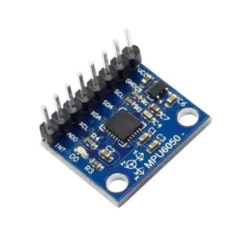
- MPU6050 IMU
- BNO055 IMU
- Breadboard and Jumper Wires
- STM32CubeIDE
- Madgwick filter source code
Steps
- Connect the IMUs to the STM32
- Connect the MPU6050:
VCC -> 3.3V GND -> GND SDA -> SDA (I2C Data) SCL -> SCL (I2C Clock) - Connect the BNO055:
- Set Up STM32CubeIDE
- Create a new STM32 project in STM32CubeIDE.
- Enable the I2C peripheral in the Pinout tab.
- Configure the I2C settings (e.g., speed, addressing mode).
- Generate the project files.
- Install the Madgwick Filter
- Download the Madgwick filter implementation.
- Add the source files to your STM32 project.
- Include the Madgwick header in your main program:
#include "MadgwickAHRS.h" - Initialize I2C and IMUs
HAL_I2C_Init(&hi2c1); // Assuming hi2c1 is your I2C handle // Initialize MPU6050 MPU6050_Init(); // Initialize BNO055 BNO055_Init(); - Read Data from the IMUs
float accelData[3], gyroData[3], magData[3]; MPU6050_ReadAccel(accelData); MPU6050_ReadGyro(gyroData); BNO055_ReadMag(magData); - Compute Quaternion Orientation
MadgwickQuaternionUpdate(gyroData[0], gyroData[1], gyroData[2], accelData[0], accelData[1], accelData[2]); - Output the Quaternion
float q[4]; MadgwickGetQuaternion(q); printf("Quaternion: %f %f %f %fn", q[0], q[1], q[2], q[3]);
      VCC    -> 3.3V
      GND    -> GND
      SDA    -> SDA (I2C Data)
      SCL    -> SCL (I2C Clock)
Troubleshooting
- IMU Not Responding: Check the wiring connections and ensure the I2C addresses of the devices are correct.
- Data Inconsistencies: Verify the sensor initialization functions and ensure they are returning success.
- Incorrect Quaternion Output: Check the Madgwick filter implementation and ensure the input data is correct and properly scaled.
Conclusion
In this tutorial, we successfully read data from the MPU6050 and BNO055 IMUs via I2C and computed the quaternion-based orientation using the Madgwick filter. This setup can be used in various applications such as robotics, drones, and motion tracking systems. For further improvements, consider implementing sensor fusion techniques for enhanced accuracy.