Introduction
Pulse Width Modulation (PWM) is a technique used to control the brightness of LEDs and the speed of DC fans by varying the duty cycle of the signal. In this tutorial, we will implement PWM control for DC fans and RGB LEDs using the STM32 microcontroller’s TIM2 with a frequency of 1kHz and an 8-bit resolution.
Prerequisites
- Basic knowledge of microcontrollers and embedded systems
- STM32 development board (e.g., STM32F4, STM32F1)
- STM32CubeIDE installed
- USB-to-Serial converter (if necessary for debugging)
- DC fan and RGB LEDs
Parts/Tools
- STM32 Development Board
- DC Fan
- RGB LED
- Jumper wires
- Soldering equipment (optional)
Steps
- Set Up STM32CubeIDE
- Launch STM32CubeIDE.
- Create a new STM32 project by selecting your microcontroller.
- Configure TIM2 for PWM
- In the “Pinout & Configuration” tab, select TIM2.
- Set TIM2 to ‘PWM Generation CH1’, CH2, CH3, and CH4 for RGB LEDs.
- Configure the timer settings:
- Prescaler: 839 (for 1kHz with a 84MHz clock)
- Period: 255 (for 8-bit resolution)
- Initialize PWM in Code
- Go to the “Project” menu and open “Generated Code”.
- In
stm32fxx_hal_tim.c, enable PWM using the HAL library:
HAL_TIM_PWM_Start(&htim2, TIM_CHANNEL_1); // for DC fan HAL_TIM_PWM_Start(&htim2, TIM_CHANNEL_2); // for Red LED HAL_TIM_PWM_Start(&htim2, TIM_CHANNEL_3); // for Green LED HAL_TIM_PWM_Start(&htim2, TIM_CHANNEL_4); // for Blue LED - Set PWM Duty Cycle
- In your main loop, set the duty cycle for each channel:
__HAL_TIM_SET_COMPARE(&htim2, TIM_CHANNEL_1, 128); // 50% duty cycle for fan __HAL_TIM_SET_COMPARE(&htim2, TIM_CHANNEL_2, 255); // 100% duty cycle for Red __HAL_TIM_SET_COMPARE(&htim2, TIM_CHANNEL_3, 128); // 50% duty cycle for Green __HAL_TIM_SET_COMPARE(&htim2, TIM_CHANNEL_4, 0); // 0% duty cycle for Blue - Connect the Hardware
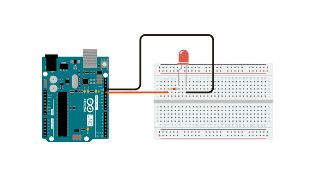
- Wire the DC fan to TIM2 channel pin (e.g., PA0).
- Wire the RGB LED’s anodes to PWM channels (e.g., PA1, PA2, PA3) and cathodes to ground through resistors.
- Upload Code and Test
- Compile the project and upload it to your STM32 board.
- Observe the fan speed and LED brightness to ensure proper operation.
Troubleshooting
- Fan Not Running:
- Check connections and ensure the fan is powered correctly.
- Verify PWM settings in the code.
- LEDs Not Lighting Up:
- Check resistor values; ensure they are suitable for the LEDs.
- Test each channel independently to isolate issues.
- Incorrect Brightness:
- Ensure the duty cycle values are within the range of 0-255.
- Check for any voltage drops in wiring connections.
Conclusion
In this tutorial, we successfully implemented PWM control for a DC fan and RGB LEDs using STM32’s TIM2 timer. By following these steps, you can easily adjust the speed of your fan and the brightness of your LEDs. This technique can be expanded further for more complex projects involving multiple PWM outputs.