Introduction
In this tutorial, we will walk through the steps to configure the STM32 TIM2 peripheral to generate a 1kHz PWM signal. This signal will be used to control the brightness of an RGB LED using DMA for smooth fading effects. We will cover the prerequisites, required parts and tools, and detailed steps to achieve the desired functionality.
Prerequisites
- Basic knowledge of STM32 microcontrollers
- STM32 development board (e.g., STM32F4Discovery)
- STM32CubeMX installed on your computer
- IDE for STM32 development (e.g., STM32CubeIDE or Keil)
- RGB LED
- Resistors for current limiting (typically 220 Ohm)
- Jumper wires
Parts/Tools
- STM32 development board
- RGB LED
- 220 Ohm resistors (3 pieces)
- Jumper wires
- Computer with STM32CubeMX and STM32CubeIDE installed
Steps
- Set up the project in STM32CubeMX
- Open STM32CubeMX and create a new project.
- Select your STM32 microcontroller or development board.
- Configure TIM2:
- In the “Timers” tab, select TIM2.
- Set the “Mode” to PWM Generation.
- Configure the “Prescaler” and “Counter Period” to achieve a 1kHz frequency:
Prescaler = 8399
Counter Period = 999
- Enable DMA for TIM2:
- In the “DMA Settings” tab, add a DMA request for TIM2.
- Select “Update” as the trigger.
- Configure the GPIO pins for the RGB LED:
- Set three GPIO pins to “PWM Output” mode (one for each color).
- Click on “Project” and name your project. Select your preferred toolchain (e.g., STM32CubeIDE).
- Click “Generate Code”.
- Write the PWM and DMA initialization code
- Open the generated project in STM32CubeIDE.
- In `main.c`, include the necessary headers:
#include "stm32f4xx_hal.h" - In the `HAL_TIM_PWM_MspInit` function, initialize the DMA:
void HAL_TIM_PWM_MspInit(TIM_HandleTypeDef* htim) { if(htim->Instance==TIM2) { __HAL_RCC_DMA1_CLK_ENABLE(); // DMA configuration code here } } - In the `main` function, start the PWM signal:
HAL_TIM_PWM_Start(&htim2, TIM_CHANNEL_1); // For Red
HAL_TIM_PWM_Start(&htim2, TIM_CHANNEL_2); // For Green
HAL_TIM_PWM_Start(&htim2, TIM_CHANNEL_3); // For Blue
- Configure the DMA to handle the color values
- Define an array for the color values:
- Set up the DMA transfer in the `main` function:
HAL_DMA_Start(&hdma_tim2_up, (uint32_t)&color_values, (uint32_t)&TIM2->CCR1, 3);
uint32_t color_values[3] = {0, 0, 0}; // Red, Green, Blue - Create a function for fading the LED
- Implement a function to change the color values over time:
- Use a loop with a delay to gradually change the brightness. Example for fading red:
for(int i = 0; i < 100; i++) { fade_LED(i, 0, 0); HAL_Delay(10); }
void fade_LED(uint32_t red, uint32_t green, uint32_t blue) { color_values[0] = red; color_values[1] = green; color_values[2] = blue; } - Compile and upload the code
- Build your project in STM32CubeIDE.
- Upload the code to your STM32 board.
Troubleshooting
- PWM signal not working: Check the TIM2 configuration in STM32CubeMX and ensure that the PWM mode is correctly set.
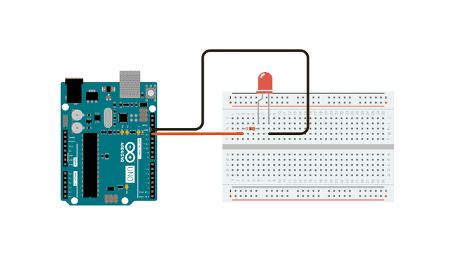
- No light from the LED: Verify the wiring and ensure that the resistors are connected correctly.
- Fading effect not smooth: Ensure the DMA is properly configured and that the color values are being updated correctly.
- Compiler errors: Check for any missing libraries or incorrect configurations in the project settings.
Conclusion
We have successfully configured the STM32 TIM2 to generate a 1kHz PWM signal to control an RGB LED with fading effects using DMA. This setup can be further extended to create more complex lighting patterns or to integrate with other peripherals in your projects. Happy coding!