Implementing a PID Controller to Regulate DC Motor Speed Using PWM Based on LED Blink Frequency Feedback on an STM32 Microcontroller
This tutorial will guide you through the process of implementing a PID controller to regulate the speed of a DC motor using PWM (Pulse Width Modulation). The feedback for the speed regulation will be obtained from an LED blink frequency. This project will utilize an STM32 microcontroller for control and monitoring.
Prerequisites
- Basic understanding of control systems and PID controllers
- Familiarity with STM32 microcontroller programming
- Knowledge of PWM and DC motors
- STM32 development board (e.g., STM32F4 or STM32F1 series)
- Development environment set up (e.g., STM32CubeIDE or Keil)
Parts/Tools
- STM32 microcontroller development board
- DC motor
- Motor driver (H-bridge or similar)
- LED
- Resistor (appropriate value for LED)
- Power supply for motor
- Connecting wires
- Computer with development tools installed
Steps
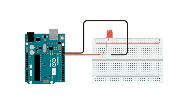
- Set up the hardware:
- Connect the DC motor to the motor driver.
- Connect the motor driver to the STM32 microcontroller.
- Connect the LED with a resistor to another GPIO pin on the STM32.
- Ensure that the power supply is correctly connected to the motor driver.
- Initialize the development environment:
- Open STM32CubeIDE or your chosen IDE.
- Create a new project for your STM32 board.
- Configure the GPIO pins used for the motor driver and the LED in the IDE.
- Write the code for PID control:
- Define the PID parameters and variables.
- Initialize PWM for motor control.
- Set up an interrupt for the LED blinking to measure frequency.
- Implement LED blinking and frequency measurement:
- Use a timer interrupt to toggle the LED.
- Count the number of toggles in a fixed time interval.
- Pass the measured frequency to the PID calculation function.
- Compile and upload the code:
- Build the project in your IDE.
- Upload the code to the STM32 microcontroller.
- Monitor the motor speed and LED blinking.
#define MOTOR_PWM_CHANNEL TIM_CHANNEL_1
#define LED_PIN GPIO_PIN_0
#define PWM_MAX 1000
#define SET_POINT 100 // desired frequency for LED blinking

float Kp = 1.0, Ki = 0.1, Kd = 0.05;
float previous_error = 0, integral = 0;

void setMotorSpeed(int speed) {
    __HAL_TIM_SET_COMPARE(&htim1, MOTOR_PWM_CHANNEL, speed);
}

void calculatePID(float measured_value) {
    float error = SET_POINT - measured_value;
    integral += error;
    float derivative = error - previous_error;

    float output = Kp * error + Ki * integral + Kd * derivative;
    setMotorSpeed((int)output);

    previous_error = error;
}
void HAL_TIM_PeriodElapsedCallback(TIM_HandleTypeDef *htim) {
    static int count = 0;
    if (htim->Instance == TIM2) { // Assume TIM2 is used for LED blinking
        HAL_GPIO_TogglePin(GPIOB, LED_PIN);
        count++;
    }

    if (count >= 1000) { // check frequency every second
        calculatePID(count); // Pass the measured frequency
        count = 0;
    }
}
Troubleshooting
- Motor does not spin: Check power connections and ensure the motor driver is functioning.
- LED does not blink: Verify the GPIO configuration for the LED and ensure the timer is set up correctly.
- PWM output is not correct: Recheck the PWM pin configuration and ensure the timer settings are correct.
- PID control is unstable: Tweak Kp, Ki, and Kd values to achieve stable control.
Conclusion
In this tutorial, you have learned how to implement a PID controller to regulate the speed of a DC motor using PWM based on the feedback from an LED blink frequency. With proper tuning of the PID parameters, you can achieve precise control over the motor speed. Experiment with different values and configurations to enhance your understanding of PID control systems.