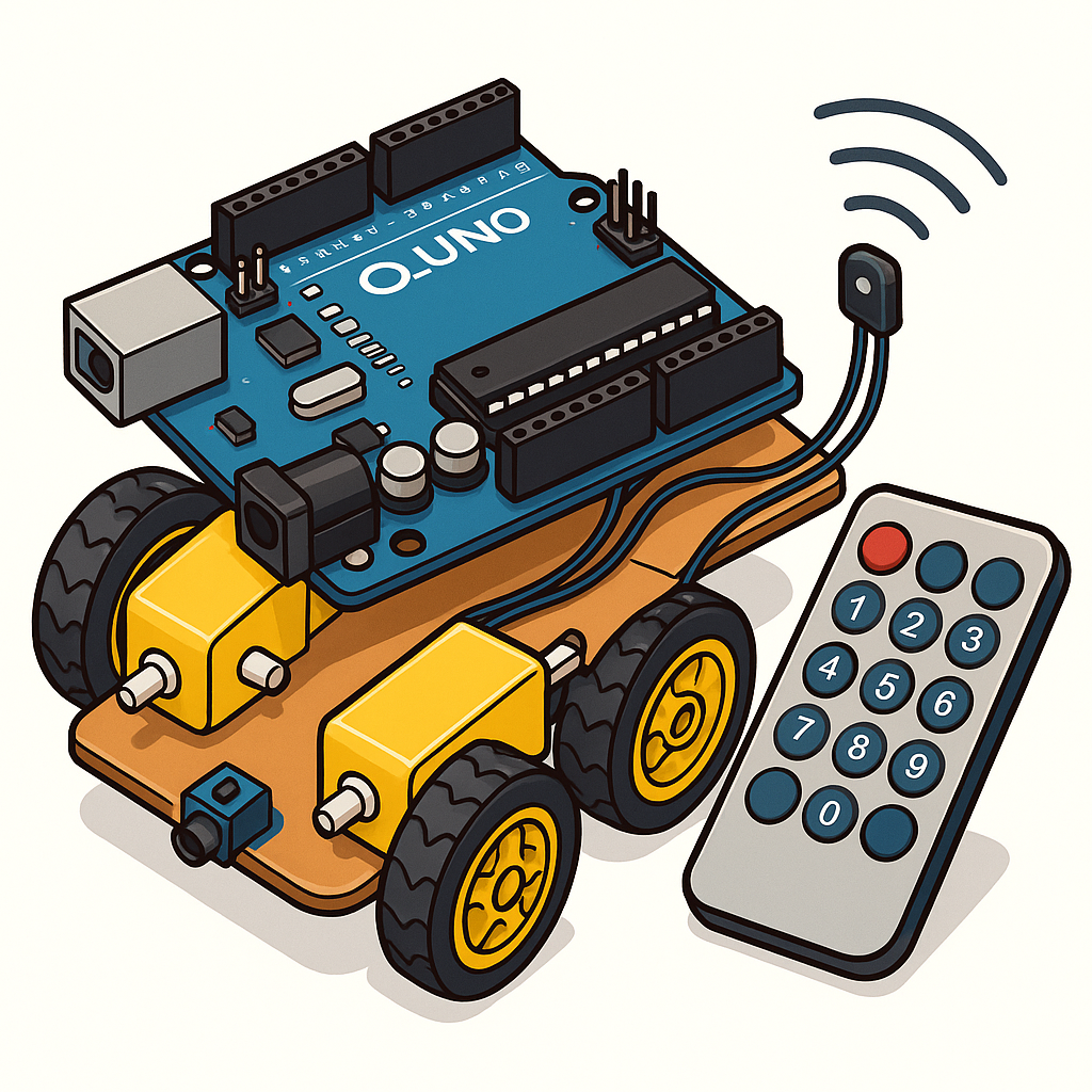
In this project, you will build a simple 2-wheel Arduino-based remote-controlled car using two DC motors, a MAX14870 dual motor driver, and an Elegoo IR remote. The car will respond to directional commands (forward, reverse, left, right) sent from the IR remote. The motors only move while a button is pressed, making control intuitive and responsive.
By the end of this guide, you will have:
- A fully wired and tested Arduino-powered RC car
- IR-based directional control for motion
- Motor driver integration with safe enable/disable handling
Required Parts For This Tutorial:
– Elegoo Starter Kit : https://amzn.to/3HiU1VX
– Will have Remote, Arduino/Elegoo Uno, and IR Receiver
– MAX14870 PWM Motor Drivers: https://www.pololu.com/product/2961
– DC Motor/Wheel Combo: https://amzn.to/45p8Sr2
System Architecture
Block Diagram:
[IR Remote] → [IR Receiver] → [Arduino UNO] → [MAX14870 Motor Driver] → [DC Motors]
The IR remote sends encoded signals to the IR receiver module.
The Arduino decodes the signal and determines the required motion.
Commands are sent to the MAX14870 motor driver, which powers the left and right DC motors.
Motion stops automatically if no valid command is received for 150 ms.
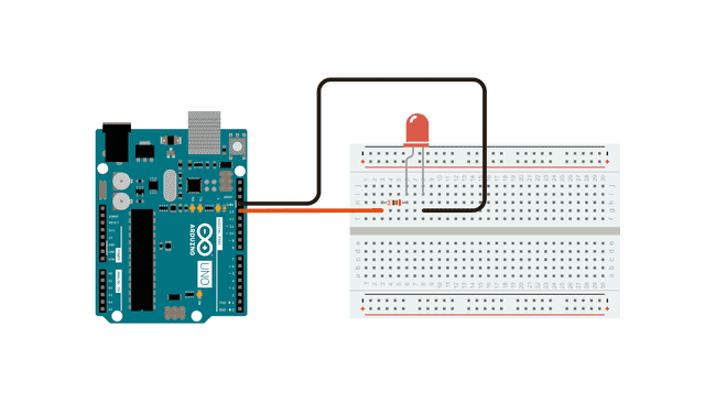
Hardware Setup
Wiring Connections
The following table maps the Arduino pins from the code to the actual hardware:
| Function | Arduino Pin | Motor Driver Pin |
|---|---|---|
| Left Motor Driver PWM | D5 | PWM input for Left motor |
| Left Motor Driver DIR | D7 | Direction input for Left motor |
| Left Motor Driver EN (optional) | D4 | Enable input for Left motor (active-low, so HIGH = enabled) |
| Right Motor Driver PWM | D6 | PWM input for Right motor |
| Right Motor Driver DIR | D8 | Direction input for Right motor |
| Right Motor Driver EN (optional) | D9 | Enable input for Right motor (active-low, so HIGH = enabled) |
| IR Receiver | D2 | Signal pin from IR receiver |
Power Connections:
- Motor driver VIN → Arduino 5V Rail
- Motor driver VM -> Battery ~7V or other power supply. The motors work from ~4-7V
- Motor driver GND → Battery negative and Arduino GND
- Motor driver M1 + M2 → DC motors + and – (For both Left and Right)
- Arduino powered via USB for programming, then switched to battery Vin if standalone
- Make sure all Grounds are connected together
- IR Receiver R -> Arduino 5V Rail
- IR Receiver G -> Gnd Rail
- IR Receiver Y -> Arduino D2
Firmware/Software Bring-Up
Toolchain Setup
- Install Arduino IDE from arduino.cc
- Install the IRremote (by shirriff, zt30, ArminJo) library:
- Open Arduino IDE → Tools → Manage Libraries
- Search for IRremote and install
Upload Code
Copy the following full sketch into Arduino IDE and upload to the UNO:
/* Full Remote Control Car Sketch */

#include <Arduino.h>
#include <IRremote.hpp>

// ---------- Pins ----------
constexpr uint8_t IR_PIN = 2;

// Left motor
constexpr uint8_t L_PWM = 5;
constexpr uint8_t L_DIR = 7;
constexpr uint8_t L_EN  = 4;   // active-low enable (HIGH = enabled)

// Right motor
constexpr uint8_t R_PWM = 6;
constexpr uint8_t R_DIR = 8;
constexpr uint8_t R_EN  = 9;   // active-low enable (HIGH = enabled)

// ---------- IR codes ----------
#define IR_UP     0xB946FF00
#define IR_RIGHT  0xBC43FF00
#define IR_DOWN   0xEA15FF00
#define IR_LEFT   0xBB44FF00

// ---------- Motor helper ----------
struct Max14870Motor {
  uint8_t pwm, dir, en;
  Max14870Motor(uint8_t pwm_, uint8_t dir_, uint8_t en_)
    : pwm(pwm_), dir(dir_), en(en_) {}

  void begin() {
    pinMode(pwm, OUTPUT);
    pinMode(dir, OUTPUT);
    pinMode(en, OUTPUT);
    digitalWrite(en, HIGH); // enable outputs
    analogWrite(pwm, 0);    // start braked
  }

  void set(int16_t speed) {
    speed = constrain(speed, -255, 255);
    if (speed == 0) {
      analogWrite(pwm, 0); // brake
      return;
    }
    if (speed > 0) {
      digitalWrite(dir, HIGH);
      analogWrite(pwm, speed);
    } else {
      digitalWrite(dir, LOW);
      analogWrite(pwm, -speed);
    }
  }
};

Max14870Motor left (L_PWM, L_DIR, L_EN);
Max14870Motor right(R_PWM, R_DIR, R_EN);

// ---------- Control ----------
int16_t baseSpeed = 160;
unsigned long lastCmdTime = 0;
const unsigned long timeoutMs = 150;  // stop motors if no command for 150 ms

void setup() {
  Serial.begin(115200);
  left.begin();
  right.begin();
  IrReceiver.begin(IR_PIN, ENABLE_LED_FEEDBACK);
  Serial.println(F("IR pulse motor control ready."));
}

void applyStop()        { left.set(0); right.set(0); }
void applyForward()     { left.set(baseSpeed); right.set(baseSpeed); }
void applyReverse()     { left.set(-baseSpeed); right.set(-baseSpeed); }
void applyTurnLeft()    { left.set(-baseSpeed); right.set(baseSpeed); }
void applyTurnRight()   { left.set(baseSpeed); right.set(-baseSpeed); }

void handleIR(uint32_t raw) {
  switch (raw) {
    case IR_UP:    applyForward(); break;
    case IR_DOWN:  applyReverse(); break;
    case IR_LEFT:  applyTurnLeft(); break;
    case IR_RIGHT: applyTurnRight(); break;
    default:       return;
  }
  lastCmdTime = millis();  // refresh timeout
}

void loop() {
  if (IrReceiver.decode()) {
    uint32_t raw = IrReceiver.decodedIRData.decodedRawData;
    if (raw != 0x0 && raw != 0xFFFFFFFF) { // ignore noise & repeats marker
      handleIR(raw);
    }
    IrReceiver.resume();
  }

  // stop if no command recently
  if (millis() - lastCmdTime > timeoutMs) {
    applyStop();
  }
}
Integration Process
- Mount the DC motors on your chassis and connect them to the MAX14870 outputs.
- Wire the motor driver inputs to Arduino as listed in the wiring table.
- Connect the IR receiver signal pin to Arduino D2, with VCC to 5V and GND to GND.
- Load the Arduino with the sketch and open the Serial Monitor at 115200 baud.
- Press buttons on the remote to verify movement.
Troubleshooting
- If motors do not move, check EN pins (on the MAX14870 chip, they are configured so that it is always on, but check anyways with a multimeter).
- If direction is reversed, swap motor wires.
- If IR remote does not register, check baud monitor for received codes. Edit the #define statements accordingly.
Testing
- Press VOL+: Both motors forward
- Press VOL-: Both motors reverse
- Press |<< Car spins left (one motor forward, one backward)
- Press >>|: Car spins right (opposite motor directions)
- Release button: Car stops automatically
Expected behavior: Motors only run while button is held.
You now have a working Arduino-powered remote-controlled car using an Elegoo IR kit, MAX14870 motor driver, and simple DC motors. The system is responsive, safe, and easy to extend into more advanced robotics projects. From here, you can add smarter control methods, better chassis, or even autonomous driving features.
Happy hacking!
Next Steps:
– Can you integrate an Ultrasonic sensor to do simple collision avoidance?
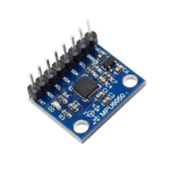
– Can you add an IMU to track acceleration and gyroscopic data?