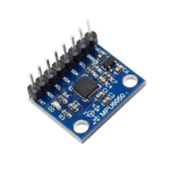
The MPU6050 is a great 6 DOF ( degree of freedom ) IMU that allows a developer to gather gyroscopic and accelerometer data together. You can get the breakout board for extremely cheap here: https://amzn.to/418sg96
1. Overview & Goals
The MPU6050 is a popular 6-axis MEMS sensor combining a 3-axis accelerometer and 3-axis gyroscope. It communicates over I²C and is widely used in robotics, drones, gesture detection, and stabilization systems.
This tutorial shows how to:
- Wire up the MPU6050 with both STM32 and Arduino.
- Configure the sensor registers.
- Read accelerometer and gyroscope data.
- Verify data output via UART/Serial Monitor.
2. System Architecture
   +-------------+        +----------------+         +-------------+
   |   MPU6050   | <----> |   MCU (STM32   | <-----> |   PC/Serial |
   | Accel+Gyro  |  I²C   | or Arduino)    |  UART   |  Monitor    |
   +-------------+        +----------------+         +-------------+
- Protocol: I²C (100 kHz or 400 kHz)
- Data Flow: MPU6050 → MCU → PC logging
- Control Flow: MCU initializes MPU6050 registers
3. Bill of Materials (BOM)
| Item | Example Part No. / Link | Notes |
|---|---|---|
| IMU Sensor | MPU6050 (GY-521 module) Amazon | 3.3V/5V compatible |
| Microcontroller (Option 1) | STM32F103C8T6 “Blue Pill” / Nucleo-F303K8 | For HAL-based example |
| Microcontroller (Option 2) | Arduino Uno / Nano | For quick prototyping |
| USB-UART Adapter (STM32) | CP2102 / FT232RL | Needed for serial logging |
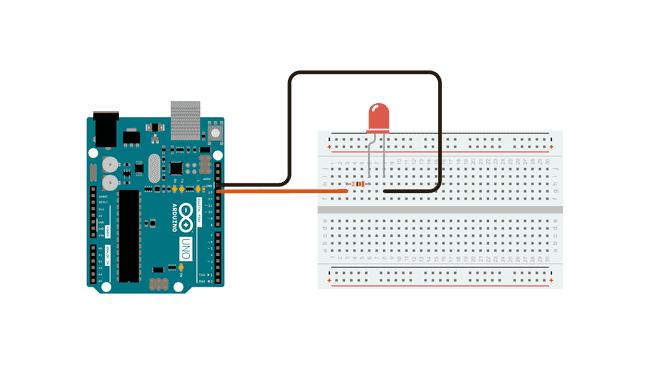
| Jumper Wires | Dupont M-M | For breadboard wiring |
| Breadboard | 830 tie-points | Optional |
| Power Supply | USB (5V regulated) | MPU6050 draws <10 mA |
4. Hardware Setup
4.1. MPU6050 → STM32F103C8T6
| MPU6050 Pin | STM32F103 Pin | Notes |
|---|---|---|
| VCC | 3.3V | Blue Pill = 3.3V logic |
| GND | GND | Common ground |
| SCL | PB6 (I²C1_SCL) | Use 4.7kΩ pull-ups |
| SDA | PB7 (I²C1_SDA) | Use 4.7kΩ pull-ups |
| INT | PA0 (optional) | Motion interrupt |
| AD0 | GND | I²C address = 0x68 |
4.2. MPU6050 → Arduino Uno
| MPU6050 Pin | Arduino Uno Pin | Notes |
|---|---|---|
| VCC | 5V | GY-521 supports 5V input |
| GND | GND | Common ground |
| SCL | A5 | I²C clock |
| SDA | A4 | I²C data |
| INT | D2 (optional) | Motion interrupt |
| AD0 | GND | I²C address = 0x68 |
5. Firmware/Software Bring-Up
5.1. STM32 HAL Firmware
Toolchain: STM32CubeIDE
Peripherals: Enable I²C1 and USART1
#include "main.h"
#include <stdio.h>

I2C_HandleTypeDef hi2c1;
UART_HandleTypeDef huart1;

#define MPU6050_ADDR (0x68 << 1)

uint8_t mpu_buf[14];

void MPU6050_Init(void) {
    uint8_t check, data;
    HAL_I2C_Mem_Read(&hi2c1, MPU6050_ADDR, 0x75, 1, &check, 1, 1000);
    if (check == 0x68) {
        data = 0x00; HAL_I2C_Mem_Write(&hi2c1, MPU6050_ADDR, 0x6B, 1, &data, 1, 1000);
        data = 0x10; HAL_I2C_Mem_Write(&hi2c1, MPU6050_ADDR, 0x1C, 1, &data, 1, 1000);
        data = 0x18; HAL_I2C_Mem_Write(&hi2c1, MPU6050_ADDR, 0x1B, 1, &data, 1, 1000);
    }
}

void MPU6050_Read(void) {
    HAL_I2C_Mem_Read(&hi2c1, MPU6050_ADDR, 0x3B, 1, mpu_buf, 14, 1000);
}

int main(void) {
    HAL_Init();
    SystemClock_Config();
    MX_GPIO_Init(); MX_I2C1_Init(); MX_USART1_UART_Init();

    MPU6050_Init();
    char msg[100];

    while (1) {
        MPU6050_Read();
        int16_t ax = (mpu_buf[0]<<8)|mpu_buf[1];
        int16_t ay = (mpu_buf[2]<<8)|mpu_buf[3];
        int16_t az = (mpu_buf[4]<<8)|mpu_buf[5];
        int16_t gx = (mpu_buf[8]<<8)|mpu_buf[9];
        int16_t gy = (mpu_buf[10]<<8)|mpu_buf[11];
        int16_t gz = (mpu_buf[12]<<8)|mpu_buf[13];

        sprintf(msg, "AX:%d AY:%d AZ:%d GX:%d GY:%d GZ:%d\r\n", ax, ay, az, gx, gy, gz);
        HAL_UART_Transmit(&huart1, (uint8_t*)msg, strlen(msg), 1000);
        HAL_Delay(100);
    }
}
5.2. Arduino Firmware
A) Raw Register Access
#include <Wire.h>
#define MPU6050_ADDR 0x68

void setup() {
  Serial.begin(115200);
  Wire.begin();

  Wire.beginTransmission(MPU6050_ADDR);
  Wire.write(0x6B); Wire.write(0x00); Wire.endTransmission(true);

  Wire.beginTransmission(MPU6050_ADDR);
  Wire.write(0x1C); Wire.write(0x10); Wire.endTransmission(true);

  Wire.beginTransmission(MPU6050_ADDR);
  Wire.write(0x1B); Wire.write(0x18); Wire.endTransmission(true);

  Serial.println("MPU6050 ready");
}

void loop() {
  Wire.beginTransmission(MPU6050_ADDR);
  Wire.write(0x3B);
  Wire.endTransmission(false);
  Wire.requestFrom(MPU6050_ADDR, 14, true);

  int16_t ax = (Wire.read()<<8)|Wire.read();
  int16_t ay = (Wire.read()<<8)|Wire.read();
  int16_t az = (Wire.read()<<8)|Wire.read();
  int16_t temp = (Wire.read()<<8)|Wire.read();
  int16_t gx = (Wire.read()<<8)|Wire.read();
  int16_t gy = (Wire.read()<<8)|Wire.read();
  int16_t gz = (Wire.read()<<8)|Wire.read();

  Serial.print("AX: "); Serial.print(ax);
  Serial.print(" AY: "); Serial.print(ay);
  Serial.print(" AZ: "); Serial.print(az);
  Serial.print(" GX: "); Serial.print(gx);
  Serial.print(" GY: "); Serial.print(gy);
  Serial.print(" GZ: "); Serial.println(gz);

  delay(200);
}
B) Using Arduino Library
#include <Wire.h>
#include <MPU6050.h>

MPU6050 mpu;

void setup() {
  Serial.begin(115200);
  Wire.begin();
  mpu.initialize();

  if (mpu.testConnection())
    Serial.println("MPU6050 OK");
  else
    Serial.println("MPU6050 FAIL");
}

void loop() {
  int16_t ax, ay, az, gx, gy, gz;
  mpu.getMotion6(&ax,&ay,&az,&gx,&gy,&gz);

  Serial.print("AX="); Serial.print(ax);
  Serial.print(" AY="); Serial.print(ay);
  Serial.print(" AZ="); Serial.print(az);
  Serial.print(" GX="); Serial.print(gx);
  Serial.print(" GY="); Serial.print(gy);
  Serial.print(" GZ="); Serial.println(gz);

  delay(200);
}
6. Testing
- Upload the code.
- Open Serial Terminal (
115200 baud). - Place the board flat: expect Z-axis accel ≈ +1g.
- Rotate/move board: accel & gyro readings should change accordingly.
7. Troubleshooting
- No I²C ACK? → Check pull-ups, confirm address (
0x68or0x69). - Random data? → Ensure endianess is correct, check supply voltage.
- Gyro drift? → Perform calibration (read bias at startup).
8. Performance Notes
- STM32 = higher speed, FIFO buffer, RTOS-ready.
- Arduino = easier for beginners, good for logging + prototyping.
- For stable orientation → use Madgwick/Mahony sensor fusion filters.
9. Next Steps
- Add Bluetooth (HC-05/ESP32) for wireless motion tracking.
- Implement 3D visualization in Processing/Python.
- Upgrade to MPU9250 for full 9-DOF (adds magnetometer).